Film 03 · Inverse design
Who moved the laser spot?
Aim a laser at a target ten metres away. With the instrument cold, the beam lands dead centre. Switch on a nearby coil and the spot drifts a millimetre. You can bring it back with the aiming screw. The problem shows up when you switch the coil off again.
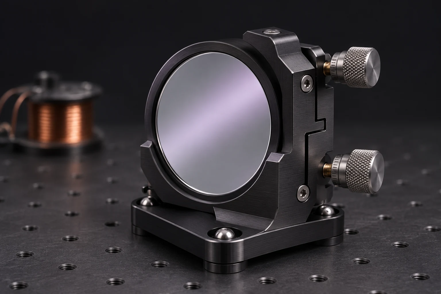
The coil is drawing the power it’s supposed to draw. The mirror is reflecting the beam exactly as it should. The instrument still fails its pointing test. Which part would you change?
What the aiming screw can fix
On this simulated bench, the 40 W coil warms the support under the mirror. The support expands. A thin flexible joint, called a flexure, passes some of that motion to the mirror and tips it by 50 microradians. A reflected ray turns through twice the angle of the mirror. Over ten metres, that puts the warm spot a millimetre from the cold one.
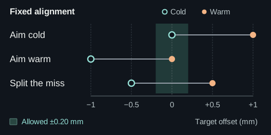
The beam has to land within 0.20 mm of centre at both temperatures. Aim it warm and it misses cold. Split the difference and it misses by 0.50 mm each way. The allowable band is only 0.40 mm wide, and the spots are a full millimetre apart. The screw can slide them across the target together. To get both inside the band, something has to bring them closer together.
How a pointing error ends up on two drawings
The optics engineer sees the miss at the target. The electrical engineer still needs 40 W at the coil. Somebody has to work out which parts they can change while honouring both commitments.
Engineers have been optimizing optical and mechanical parts together for years. In 2018, Koppen and colleagues used the performance of a two-mirror system to optimize several components at once, within design regions chosen for the study. In 2026, the MecSOAgent researchers showed how software could turn written requirements for a mechanical system into design variables, constraints and an executable optimization problem. [1] [2]
Impulse starts with the failed check on the assembly in front of it. It follows the physical relationships back from the miss and checks which features the owner has allowed it to edit. On this bench you can follow both branches yourself. A larger heat sink keeps the support cooler, so it expands less. A different flexure transmits less of that expansion to the mirror. Both can bring the spots closer together while the coil runs at full power.
Coupled optomechanical graph · 40 W load
Choose a view of the optical bench
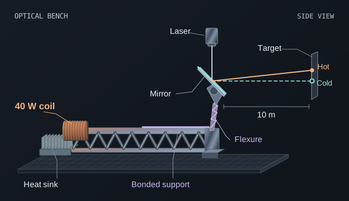
From coil to spot (Forward physics). Heat from the 40 W coil expands the bonded support. The flexure transmits that motion to the mirror, tipping the beam by 1.00 mm at 10 m.
Try one small change to each control
| Trial change | Separation | Effect |
|---|---|---|
| Reduce the hot load to 39 W | 0.9750 mm | Changes the specified test |
| Shift the aim by +0.10 mm | 1.0000 mm | Moves both spots equally |
| Add 1 cm² of sink area | 0.9816 mm | Reduces temperature rise |
| Transmit 99% of the reference motion | 0.9900 mm | Reduces mirror tilt |
Where one extra watt matters most
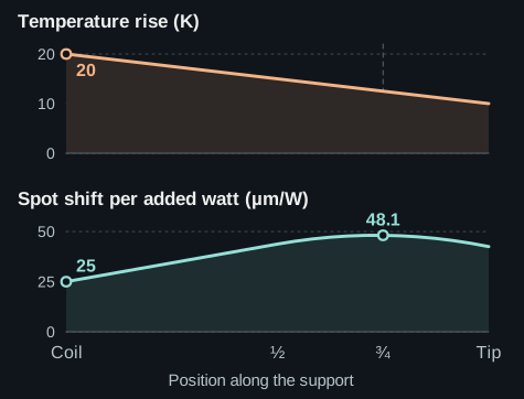
The coil is the hottest point on the support, about 20 degrees above ambient. Add a watt at the coil and the spot moves another 25 micrometres. Add the same watt three-quarters of the way along the support, where it’s cooler, and the spot moves about 48 micrometres.
The coil sits next to a heat sink. Farther along, more of the expansion in the bonded support reaches the mirror. That’s why the hottest point and the point of greatest optical sensitivity are in different places.
The green curve comes from an adjoint calculation. Starting from the quantity we care about, the spot position, one backward solve gives its local sensitivity to heat added at many locations. To check a hardware change, we run the revised bench forward again, once cold and once warm. [3]
The change order
Give each design its best single aiming-screw setting. The requirement is a maximum miss of 0.20 mm across the two loads.
| Change to the bench | Worst miss |
|---|---|
| Original 40 cm² heat sink and flexure | 0.5000 mm |
| Increase the sink to 72 cm² | 0.3125 mm |
| Change the flexure to transmit 60% of the original motion | 0.3000 mm |
| Make both changes together | 0.1875 mm |
With both changes, the cold spot lands at −0.1875 mm and the warm spot at +0.1875 mm. The optics engineer can review one change order covering the sink and the flexure, with a predicted reading for each operating condition.
Interactive design election · At 1:45 in the film
Which requirement can change?
Now suppose the customer has room for only 50 cm² of heat sink. Even with the most isolating flexure allowed (60% transfer), the best fixed aim misses by about 0.253 mm. Impulse puts two concrete, priced choices in front of the owner:
Awaiting the owner’s choice. Under the 50 cm² cap and ±0.200 mm requirement, the best permitted design misses by 0.2526 mm at each end of the load range.
An extra 16.7 cm² might be easy to accommodate on a lab bench and impossible inside a customer’s enclosure. Impulse can calculate exactly what each choice buys. The customer gets to decide which specification they’re willing to change.
The calculation
Write a = A / (40 cm²) for the relative sink area and m for the fraction of the original motion transmitted by the flexure. After the best fixed alignment, the worst miss on this bench is m / (1.5a + 0.5) mm. Substituting A = 50 cm² and m = 0.60 gives 0.25263 mm.
Research cited
- S. Koppen and colleagues (2018). Topology optimization of multicomponent optomechanical systems for improved optical performance.
- C. Zhu and colleagues (2026). A Multiagent Architecture of Requirement-Driven Mechanical System Optimization.
- OpenMDAO. How Total Derivatives are Computed, Theory Manual.
Read the timed transcript
- A laser shines on a target ten metres from a mirror. Watch the dot when a coil switches on.
- The dot drifts a millimetre. What moved it?
- Start at the coil and follow the heat.
- The coil warms the truss. As the bonded section expands, the flexure tips the mirror.
- Tilt a mirror through one angle and its reflected ray turns through twice that angle.
- Fifty microradians at the mirror becomes a one-millimetre miss at the target.
- Re-aim at full power. The warm spot comes back to the centre.
- Now switch the coil off. With that same aim, the cold spot misses on the opposite side.
- Split the difference. Even the best fixed aim misses by half a millimetre at each load.
- Which inputs can move the spot? Draw an arrow wherever one quantity depends on another.
- Start at the spot and follow those arrows upstream. Hold the specified load and the aim fixed.
- The search reaches the heat sink and the flexure. How much influence does each have?
- An adjoint starts with the output we care about and computes its sensitivity to many inputs.
- Orange shows temperature. Cyan shows how far the spot moves for one extra watt added at each location.
- The coil is hottest. The greatest displacement per added watt occurs farther along the truss.
- At this design, increasing sink area and reducing flexure transfer both pull the warm spot toward centre.
- Each point on the left is a design. The green region meets the pointing limit at both loads after a fixed re-aim.
- Try all the extra cooling. Now try the flexure alone. Each still misses.
- Change both together. Set the aim once, then solve the forward model again at zero and forty watts.
- Both spots land inside the limit. This edit can commit under the original requirements.
- A second brief caps the heat sink at fifty square centimetres. Watch the allowed region shrink.
- Even at the best permitted setting, the spot misses by 0.253 mm. The owner asked for at most 0.200.
- This is a design election. To keep the pointing accuracy, the owner can allow a larger heat sink.
- Or the customer can keep the smaller housing and accept a wider pointing tolerance.
- The customer says, “Keep the accuracy.” Impulse can now fit the larger heat sink.
- Impulse increases the heat-sink area from 50 to 66.7 cm². The flexure still transmits 60% of the reference motion.
- Use one fixed aim. Run the cold test, then the 40 W test. Both spots land just inside the ±0.200 mm limit.